──── Geometry-first tokamak stability program
A discrete corridor hypothesis for tokamak stability.
HCE Fusion tests whether a bounded region of plasma geometry corresponds to systematically improved stability, and whether a reactor can stay inside that region with discrete rail-to-rail trim control.
The program is not presented as new plasma physics. It is a geometry-driven confinement optimization hypothesis, designed to be tested with the equilibrium, transport, and gyrokinetic tools the fusion community already uses.
Primary cosmology benchmark
0.11 RMS |z|
Five-row primary density and background set against Planck 2018, with a maximum single-observable deviation of 0.25σ at h.
0
fitted cosmological parameters in the reported benchmark
0.37
BAO χ²/N across BOSS DR12 and eBOSS DR16 distance ratios
60
cross-domain anchors in the precision lattice
38
orders of magnitude claimed across the validation span
01 · The problem
Fusion progress is real. Turbulence-driven transport remains the central constraint.
Magnetic confinement has matured across equilibrium control, heating, fueling, and diagnostics. The barrier that still separates today's tokamaks from reactor-grade confinement is anomalous transport driven by plasma-scale turbulence.
Parameter space
High dimensional
Shape, current profile, pressure profile, heating, and edge conditions interact across a difficult continuous search space.
Operational window
Narrow margins
Small deviations can move a plasma from favorable confinement toward transport loss, displacement, or control burden.
Control cost
Continuous effort
Conventional controllers regulate against drift continuously. HCE asks whether discrete geometry rails can reduce actuation cost.
The program asks a focused question: does a discrete operating structure exist beneath the continuous plasma-control problem?
02 · The approach
A bounded corridor with discrete operating rails.
The HCE approach starts with plasma geometry, not continuous optimization. It identifies a bounded stability corridor, an optimal interior band, and a small set of named operating rails inside that corridor.
Instead of regulating continuously against every drift, the controller is framed as a state machine that navigates between rails using finite, bounded trim actions.
Corridor
A geometry-defined region of plasma operating space with favorablestability properties.
A geometry-defined region of plasma operating space with favorablestability properties.
Rails
A compact set of distinguished equilibrium states, including an interior optimal band.
A compact set of distinguished equilibrium states, including an interior optimal band.
Trim catalogue
A bounded set of finite-step actions designed to move the plasma between corridor rails.
A bounded set of finite-step actions designed to move the plasma between corridor rails.
State machine
Event-driven correction replaces continuous regulation as the primary control metaphor.
Event-driven correction replaces continuous regulation as the primary control metaphor.
03 · Conceptual schematic
What the corridor looks like, in concept.
Corridor boundaries, rail coordinates, trim catalogues, and quantitative parameter values are confidential. The schematic below shows the shape of the hypothesis, not the protected coordinates.
Cohesion corridor and monitor rails
Conceptual, not coordinate-disclosing
Conceptual, not coordinate-disclosing
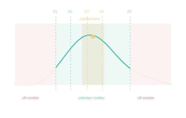
The outer band represents the corridor; the inner band represents the predicted optimum. M1-M5 are discrete monitor rails used by the trim controller.
Phase 1 result
~2.5×
stability advantage
Observed within corridor versus off-corridor configurations in reduced-model sweep.
~2.5×
stability advantage
Observed within corridor versus off-corridor configurations in reduced-model sweep.
Phase 4 result
12-18×
control efficiency
Lower actuation cost than a tuned PID baseline across four disturbance scenarios.
12-18×
control efficiency
Lower actuation cost than a tuned PID baseline across four disturbance scenarios.
Phase 2 result
Improved
equilibrium margins
Mercier stability margin increased and Shafranov shift decreased inside the corridor.
Improved
equilibrium margins
Mercier stability margin increased and Shafranov shift decreased inside the corridor.
04 · Validation status
Three computational phases are complete One remains.
The corridor hypothesis has been tested through a staged computational program using established modeling tools. The remaining bridge is gyrokinetic turbulence simulation, the standard quantitative test for transport claims.
Phase 1
Reduced-model sweep
Complete
Phase 2
MHD equilibrium
Complete
Phase 4
Discrete controller
Complete
Phase 3
Gyrokinetic transport
Phase I target
Phase 3
Gyrokinetic transport
Phase I target
Phase 3
Gyrokinetic transport
Phase I target
HCE Fusion is not a replacement for accepted plasma
modeling. It is a geometry-driven optimization hypothesis that
should be tested with the community's existing tools.
05 · Roadmap
From computational validation to deployment.
The next step is to test whether corridor configurations reduce turbulence growth rates and transport loss relative to off-corridor baselines.
Phase I · 12 months
Gyrokinetic study
Run GENE, GS2, or CGYRO against corridor and off-corridor configurations with a national lab or university plasma group.
Phase II · 24 months
Control integration
Integrate the corridor method with established plasma control and equilibrium modeling workflows.
Phase III
Software and services
Offer modeling services and stability-analysis software for fusion developers and turbulence-modeling groups.
Phase I · 12 months
Gyrokinetic study
Run GENE, GS2, or CGYRO against corridor and off-corridor configurations with a national lab or university plasma group.
06 · Engage
For technical detail, deeper
we operate under NDA.
Corridor boundaries, rail coordinates, trim catalogues, quantitative validation results, and the underlying lattice structure are protected intellectual property.
Request the technical package.
For plasma physics groups, fusion developers, and investors evaluating the fusion portfolio. The package includes validation reports, source code, figures, and the proposal structure under mutual NDA.
Discuss simulation collaboration.
The near-term need is a gyrokinetic turbulence study with a national lab, university group, or fusion program already using HPC-class transport tools.
Patent-pending technology. The HCE Multi-Band Cohesion Corridor, discrete monitor rail architecture, trim catalogue, and underlying lattice framework are subject to filed and pending patent applications. This page is conceptual; quantitative parameters are confidential and disclosed under NDA.