AI compute draw can swing by orders of magnitude within milliseconds. Mechanical tap-changers, passive filters, and bulk conversion assumptions were not specified for that load shape.
──── Corridor-based energetic step-down
A second control axis for electrical power conversion
Conventional transformers have one primary knob: the turns ratio. HCE adds structured, electronic corridor control inside the conversion path.
Energy is routed through stable harmonic pathways rather than a single bulk conversion step. The result is a transformer architecture built for AI data centers, EV fast charging, renewable integration, and isolation-critical infrastructure.
Energetic step-down model
Target efficiency
98-
99%
weighted conversion envelope
Inrush reduction
40-60%
session-aware ramp control
THD reduction
50-80%
managed inside the apparatus
Isolation mode
95-99%
01 · The problem
A century-old conversion paradigm is meeting modern load shapes.
AI clusters, EV charging sites, renewable generation, and grid modernization are all stressing transformers in ways the conventional one-step architecture was not designed to actively manage.
Non-linear load volatility
Repeated energization stress
EV fast-charging turns every session into a transformer energization event. Hardware rated for continuous service accumulates wear under repeated inrush and termination cycles.
Variable generation
Solar, wind, and storage inject harmonic-rich, bidirectional power. Conventional transformers absorb that variability; they do not route or govern it.
Procurement window
Utility modernization budgets are moving faster than transformer lead times. The replacement architecture chosen now can shape a generation of grid hardware.
02 · The approach
Replace one bulk conversion step with a structured descent.
AI clusters, EV charging sites, renewable generation, and grid modernization are all stressing transformers in ways the conventional one-step architecture was not designed to actively manage.
The conventional transformer fixes output through a single turns ratio, then relies on external hardware for harmonics, power factor, isolation, and transient behavior. HCE keeps the transformer function, but gives it an internal control grammar.
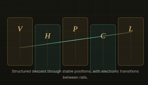
The corridor architecture separates stability positions from transport transitions. Instead of forcing every condition through one static conversion path, the apparatus chooses the corridor appropriate to the load, duty cycle, and protection state.
Conventional step vs. corridor descent
conceptual architecture, not method disclosure
Conventional
Fixed turns ratio
Mechanical tap positions
External filters
Fault behavior set by hardware limits
HCE corridor
Stable operating rails
Electronic transitions
Internal coherence and THD control
Protocol-driven safe-state demotion
The same physical platform can be graded for utility distribution, AI data centers, EV charging, renewable integration, and isolation-critical deployment.
03 · Performance envelope
What changes for the customer.
The target envelope is expressed against a conventional transformer of comparable VA rating and application grade. Values remain target specifications until qualified in the target hardware program.
Target improvement bands
ranges from the HCE transformer overview
Peak inrush
40-60%
Core loss
15-40%
Copper loss
8-25%
THD
50-80%
Efficiency
98-99%
Isolation CMR
95-99%
04 · Validation
Stress behavior has been checked at simulation scale.
The validation program tested corridor governance under normal and stress conditions, including shock events, rail-type enforcement, and demanding AI/precision workload profiles.
Trials
0,000
Monte Carlo trials under normal and stress conditions.
Containment
0%
All trials resolved within tolerance across tested conditions.
Governance
>0%
Reduction in transition-rail violations under policy.
Reproduction
0x
Independent implementations reached matching structural conclusions.
05 · Applications
Six deployment surfaces, one apparatus family.
Grid distribution
Continuous, non-contact ratio management for volatile feeders, with sub-cycle response targets and internal THD control.
AI data centers
Workload-aware corridor selection that tracks training and inference phases before demand arrives at the bus.
EV charging
Session-lifecycle protocols for inrush suppression, high-current charging corridors, and pre-demotion before termination.
Renewables and storage
Bidirectional corridor activation for charge/discharge transitions and guard corridors for intermittent generation.
Isolation and faults
Dedicated identity-regime operation for grounding, isolation, and rapid demotion to safe-state behavior.
Industrial and rail
Deterministic behavior under motor starts, traction transients, offshore deployment, and heavy-duty stress cycles.
Corridor-governed charging environment
HCE corridor conversion is designed to stabilize the upstream power environment delivered to high-current charging systems. By governing transient behavior, harmonic content, and transport-state transitions inside the conversion apparatus, the architecture targets smoother current delivery, reduced energization shock, and improved compatibility with adaptive fast-charging platforms.
Adaptive charging performance targets
06 · Product strategy
A graded platform, not a single SKU.
Grade is determined by measured performance at qualification and programmed into the unit at manufacture. Field upgrades can be handled through re-qualification rather than a full platform change.
Premium
Q
AI data centers, quantum compute, and isolation-critical infrastructure.
Target: coherence at or above 0.997; efficiency at or above 99.2%.
Advanced
A
Enterprise data centers, EV charging networks, and grid-tier distribution.
Target: coherence at or above 0.993; efficiency at or above 98.8%.
Standard
S
Commercial distribution, renewable integration, and industrial installations.
Target: coherence at or above 0.985; efficiency at or above 98.0%.
Restricted
R
Retrofit, legacy replacement, and cost-sensitive deployments.
Target: coherence at or above 0.970; efficiency at or above 96.5%.
07 · IP and status
A coordinated HCE filing position.
The transformer apparatus sits inside the HCE corridor-framework portfolio, with a root grid-voltage filing, a parent energetic step-down apparatus filing, and continuation work covering the extended dual-regime embodiment and multi-tier correction hierarchy.
Power conversion portfolio
Coverage spans distribution, substation, intertie, power quality, renewable integration, storage, FACTS, fault ride-through, and resilient infrastructure applications.
Broader framework
The same corridor logic appears across HCE computing architecture, quantum networking, pharmaceutical classification, materials, fusion, and energy-storage programs.
08 · Engage
Move from educational review to technical diligence.
Request a technical diligence session.
Under mutual NDA, HCE can walk through the filed claim structure, validation data, manufacturing grading methodology, and integration path for the applications most relevant to your organization.
Discuss deployment fit.
The most immediate fit is with utility distribution, AI data-center power, EV charging, renewable integration, isolation-critical power, and heavy industrial infrastructure.